Introduction
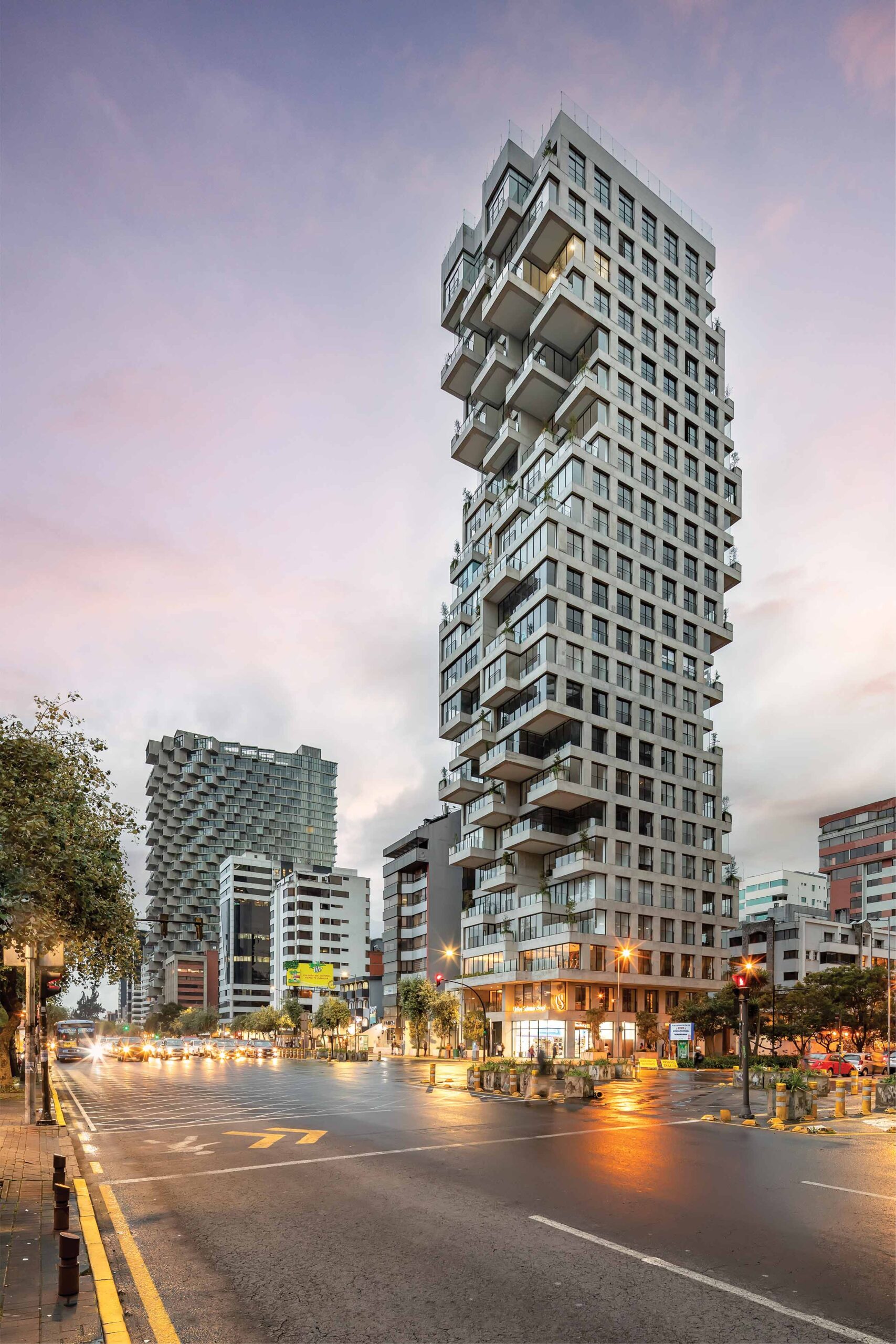
Qorner is a 26-story residential building in Quito, Ecuador, that challenges the conventional typology of high-rise towers. The project aims to create a vertical community that integrates nature, views, and social interaction. Its distinctive profile is the result of a structural system that allows each unit to have a different orientation and size, creating a variety of terraces and balconies (see Figure 1). The slabs are staggered in plan and elevation, forming a dynamic and irregular façade. The façade is clad with operable glass walls that enable natural ventilation and lighting, as well as a seamless connection between indoor and outdoor spaces. The tower’s design responds to the site’s context, climate, and culture, offering a new model of urban living in Quito.
The total area of the 98-meter structure is about 16,000 square meters, 33 percent of which is underground, with the rest allocated to upper levels. The building is located on Avenida de los Shyris and Avenida Portugal, on the north side of Quito.
The concrete used in the vertical elements has a compressive strength of 45 MPa and 35 MPa in the horizontal elements. In both cases, the modulus of elasticity is about 2.1 million kN/m2 due to special characteristics of the local aggregate. An ASTM A615 Gr60 steel reinforcement was used, with a yield strength of 420 MPa.
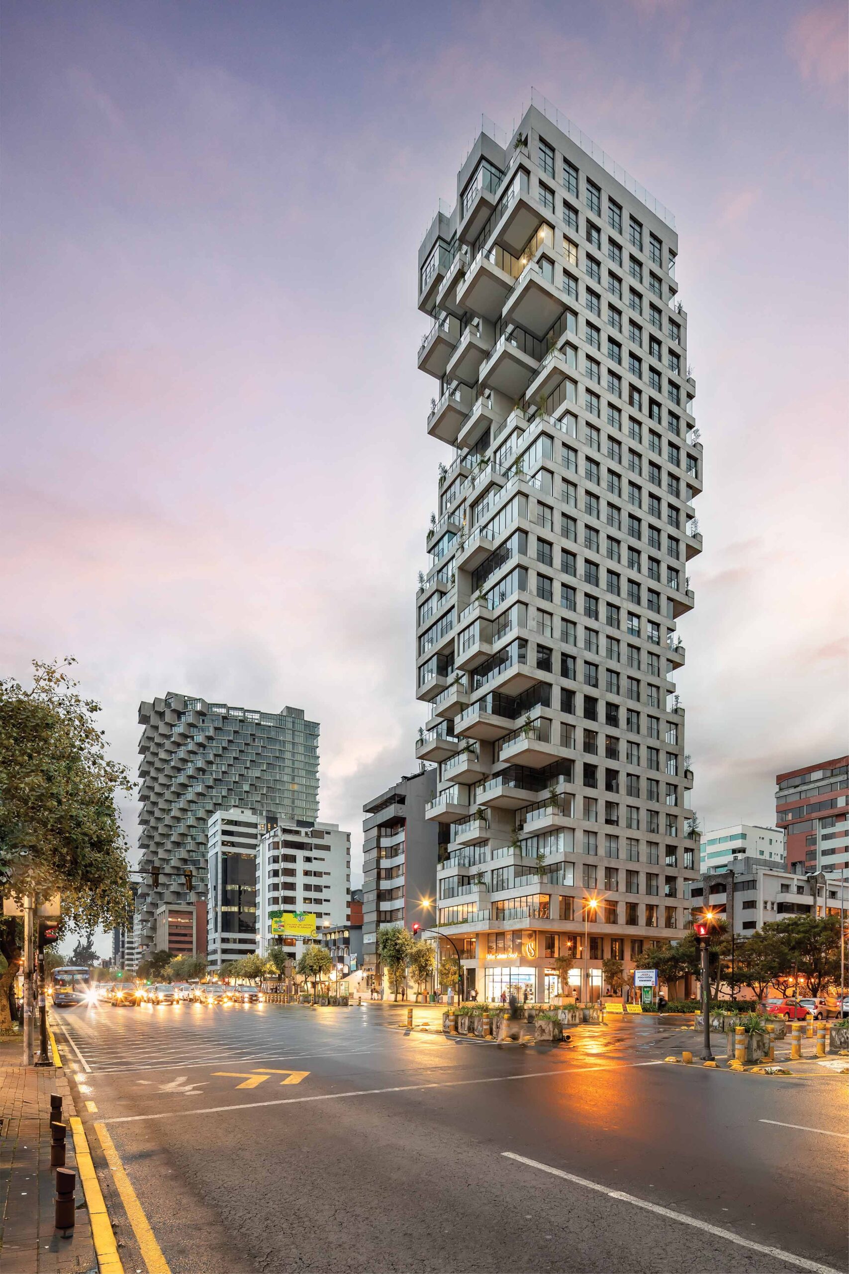
Figure 1. Qorner, Quito. © Uribe Schwarzkopf & Moshe Safdie
The floor system consists of 180-millimeterthick unbounded post-tensioned (PT) slabs supported by the façade framing, the core wall and two interior structural walls. These PT slabs were able to cover spans of up to 8.9 meters.
The lateral load-resisting system consists mainly of a reinforced-concrete (RC) core wall with diagonally reinforced coupling beams, which provides the greatest lateral stiffness and strength to the building (see Figure 2). The width of these walls at the base is up to 800 millimeters, decreasing down to 400 millimeters at the top.
The façade framing is also part of the lateral load-resisting system, providing both lateral and torsional stiffness. The foundation system corresponds to a mat slab of 1,500 millimeters’ thickness under the entire area of the building, with greater depth under the core and walls.
One of the main characteristics of the project is that, due to the limited site area, there are a lot of vertical load transfers. In Figure 3, the architectural layout of one of the tower’s floors can be seen, where all the vertical elements are highlighted in blue.
The typical underground level layout can be seen in Figure 4, where vertical elements collide with both auto circulation and parking spaces. Due to the limited site area, there was no way the auto circulation could have been moved somewhere else. This forced the designers to examine alternatives to transfer vertical loads to other structural elements, specifically:
- At the center gridline, the loads from two high-loaded vertical columns were transferred to the central core via sloped columns (see Figure 5).
- At the northern façade, two columns were transferred by way of a deep transfer beam highlighted in green (see Figure 6). The architectural layout needed an additional opening on this transfer beam, producing two additional deep beams.
- At the southern façade, the loads of the cantilevered systems highlighted in red (referred to hereafter as “multistory cantilevers”) needed to be transferred into the central frame, which is the one that effectively has a vertical continuity (see Figure 7). To do this, the construction sequence was defined as a part of the engineering design, by specifying temporary steel columns to provide support until several of the stories were already poured, and the concrete achieved a large percentage of its ultimate design strength.
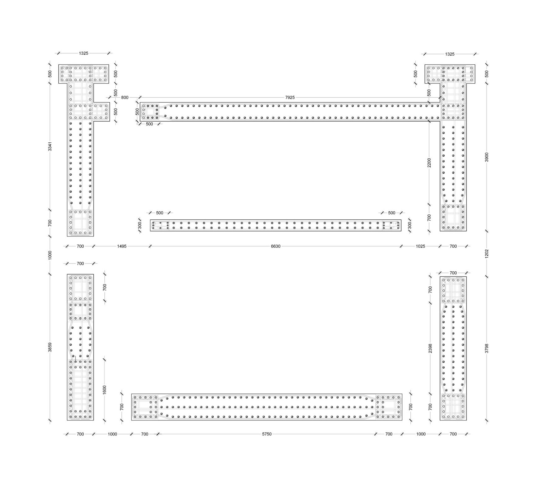
Figure 2. The lateral-load resisting system (mm).
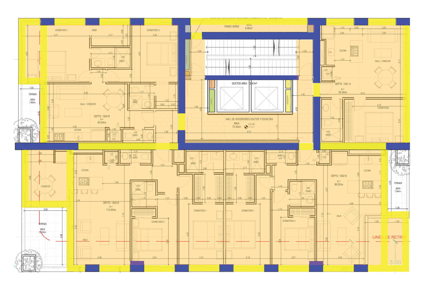
Figure 3. Vertical load transfers (highlighted in blue).
All these transfers were done with the use of structural members that unintentionally provided lateral stiffness to the building. In the center gridline, the two sloped columns act as a brace, while the two deep beams that are part of the Figure 4. Typical underground level plan. transfer beam in the northern façade could cause lateral coupling between the core wall with the rest of the façade. In the southern façade, the geometry of the structural members is such that they act as a moment frame, including the multistory cantilevers.
Because of the unintended stiffness that the transfer elements provide, all these elements would increase their internal stresses during an earthquake. On the other hand, they are key elements for the vertical load systems, and as such, they need to remain elastic, even for the maximum considered earthquake (MCE), and be treated as force-controlled elements.
The prescriptive procedures of the seismic codes, which mainly use linear analysis, usually face these challenges by compromising the seismic reduction factor or over-engineering strength factors, but these are both indirect approaches that generate much uncertainty.
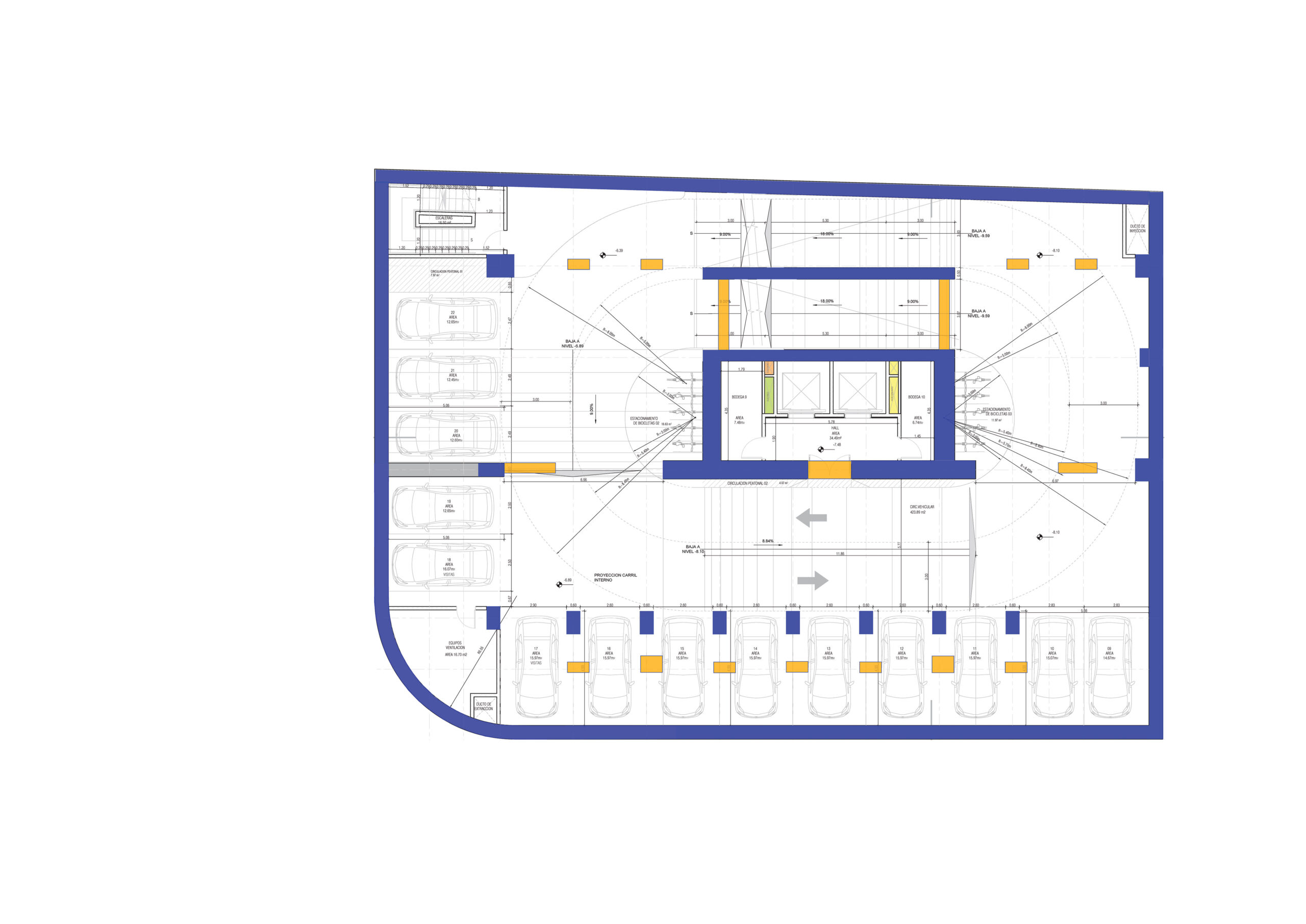
Figure 4. Typical underground level plan.
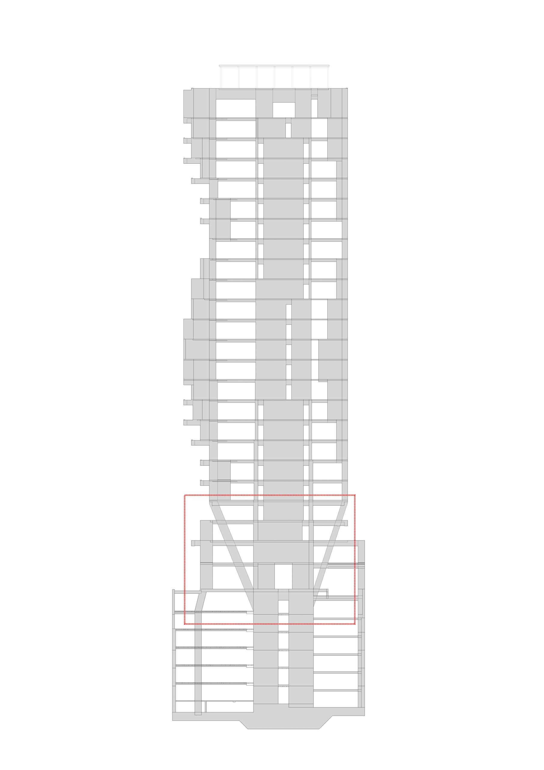
Figure 5. Section.
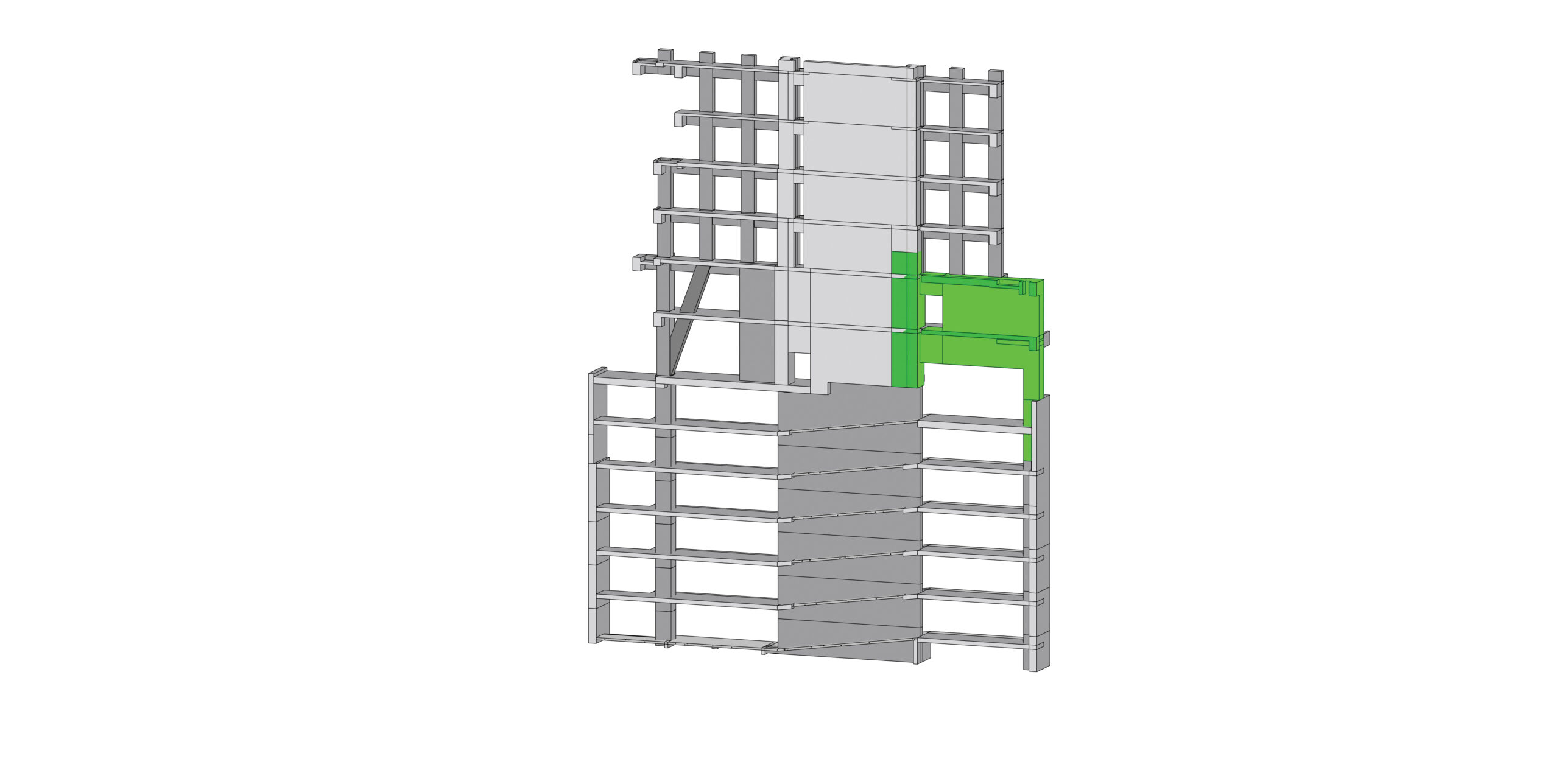
Figure 6. Deep transfer beam on northern façade.
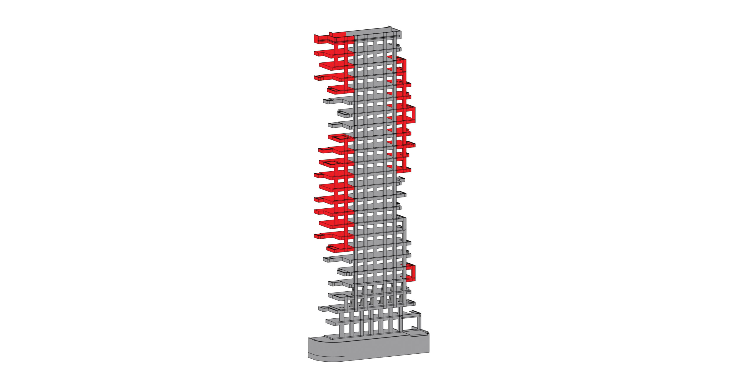
Figure 7. Cantilever load transfers on southern façade.
In this context, with all the uncertainty around seismic demand, structural response, material properties, etc., performance-based seismic design (PBSD) procedures offered a more rational and explicit check of these elements, and therefore provide a more reliable way to verify that they indeed will satisfy the intended seismic behavior.
“Performance-based seismic design (PBSD) procedures offered more rational and explicit check of the elements, and therefore provided a more reliable way to verify that they indeed will satisfy the intended seismic behavior. ”
Codes and Design Criteria
The Ecuadorian construction standard NEC-SE-DS defines the seismic demand, the response modification factor (R), the minimum base shear, the maximum allowable drifts, etc. Its focus and limits are similar to those presented in chapter 12 of ASCE7-16, with some differences like a diminution of the R factor due to structural irregularities.
The standard NEC-SE-HM defines the strength of the different reinforced concrete structural members and the seismic detailing required. It is similar to the ACI318-19 code, with a significant difference in the way the dynamic amplification factor for the core wall shear forces are calculated, resulting in large prescriptive amplification factors of 5 times the shear obtained from the factored loads (see Figure 8).
The 2018 version of the LATBSDC “An Alternative Procedure for the Seismic Analysis and Design of Tall Buildings located in the Los Angeles Region” was used as a PBSD guideline. The design criteria were the following:
1. Full local code compliment, with the exception to the dynamic shear amplification factor. This includes:
- Use of the code seismic spectrum, which is larger than the site-specific spectrum. • Use of linear modal response analysis.
- A vertical earthquake was considered.
- Capacity design for both the core wall and the façade moment frames.
2. Performance is checked with PBSD procedures. This includes:
- Site-specific response spectrum for service earthquake (Tr = 43 years) and maximum considered earthquake (MCE) (Tr = 2475 years).
- Use of non-linear dynamic analysis.
- Explicit check of global and local response, especially in the transfer elements.
Analysis and Design Strategy of Key Elements
The actual design lateral strength required by the local code was nine percent of the seismic weight in the east-west direction and eight percent of the seismic weight in the north-south direction, for fundamental crack periods of 2.4 and 3.5 seconds, in their respective analysis directions.
To maximize the strength of the sloped columns in the available space, composite construction was needed (see Figure 9).
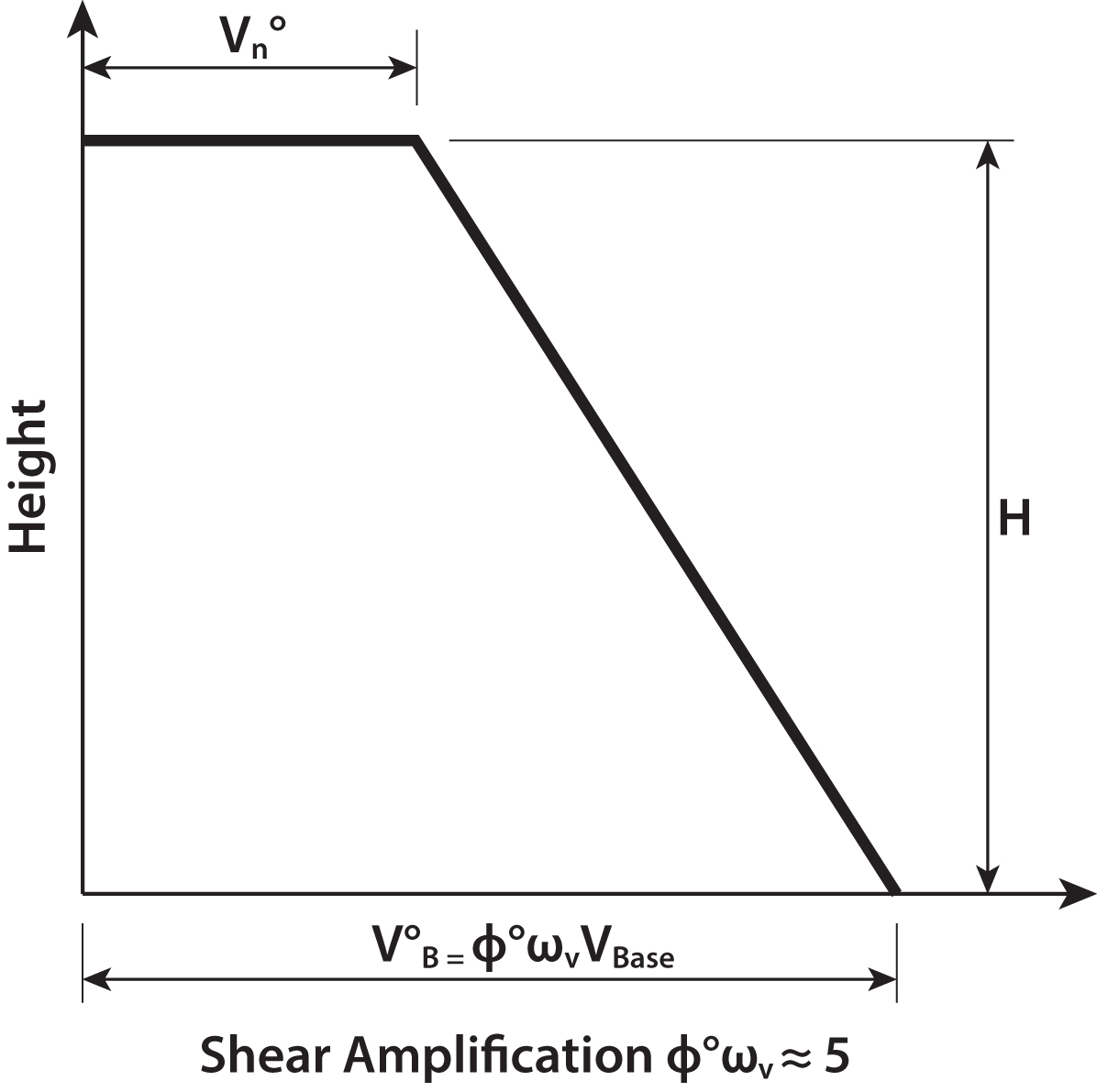
Figure 8. Factored shear loads.
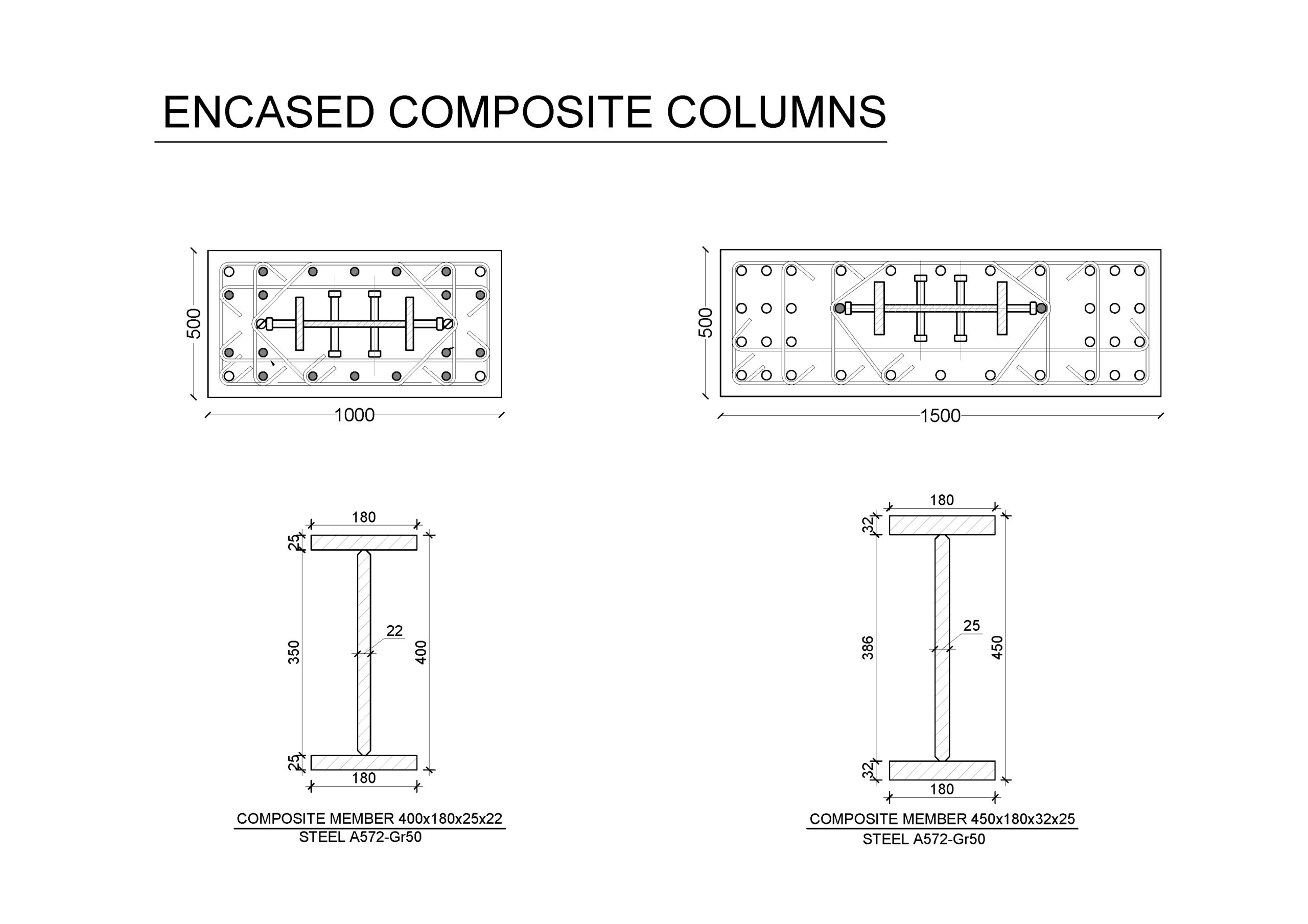
Figure 9. Encased composite columns (mm).
The sloped columns produce horizontal reactions on the floor system that are directly proportional to the axial load that these columns are carrying, specifically a tension tie at the start of the inclination and a compressive strut at the street level. In order to strengthen the structure against these reactions, the first five levels use 300-millimeter-thick traditional RC slabs with an addition of local beams acting as compression struts or tension ties.
In the northern façade transfer, despite the intention for the two deep beams to remain elastic, they were reinforced with diagonals in order to provide a ductile response without strength loss, if the earthquake demands were larger than expected.
In the southern façade, all the load resisted by the structure highlighted in red needed to be transferred to the central moment frame (see figures 10 and 11). If each story relies on itself to do that, very high bending moments strength due to gravity loads would be needed on some stories. However, if the same loads are resisted by all the stories of a specific group of cantilevers, forming a multistory cantilever system, the bending strength requirement decreases significantly, for example from 2,500 kN-m to 1,100 kN-m in section 1 or from 900 kN-m to 200 kN-m in section 2.
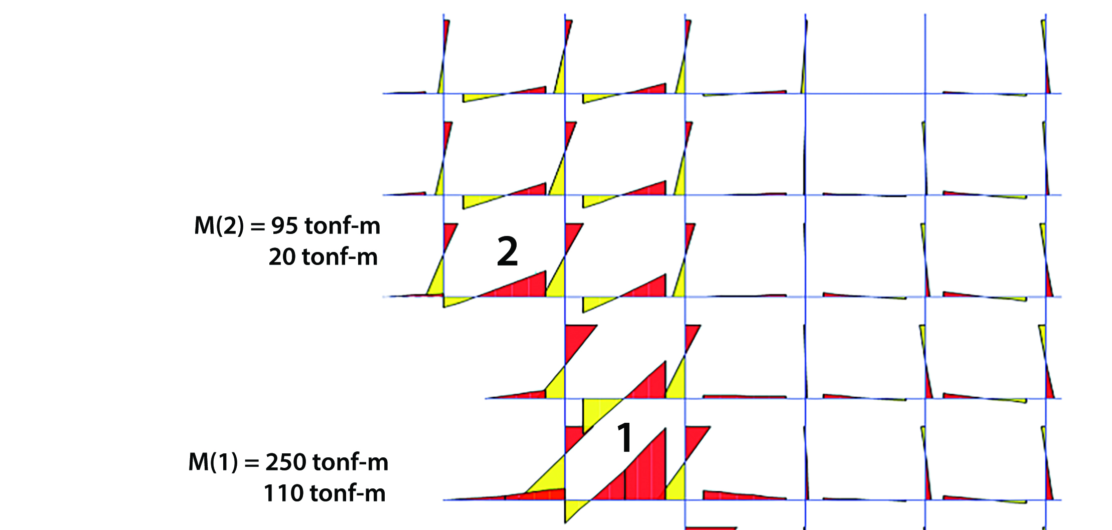
Figure 10. Cantilever bending strength.
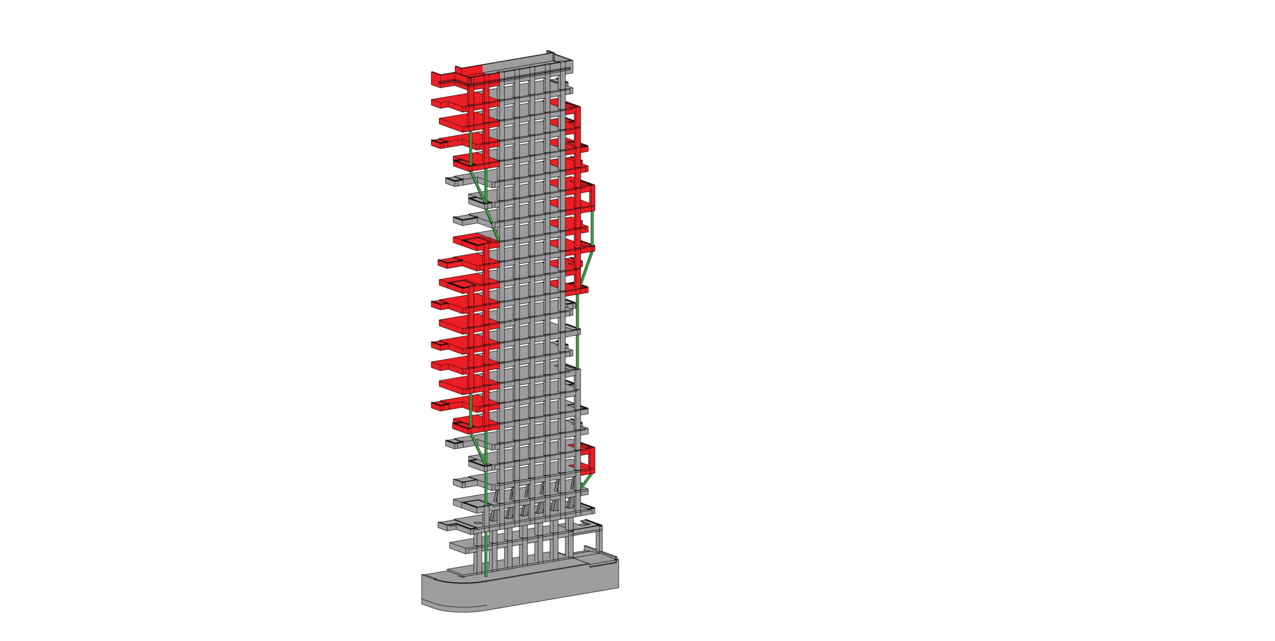
Figure 11. Cantilever load transfers on southern façade.
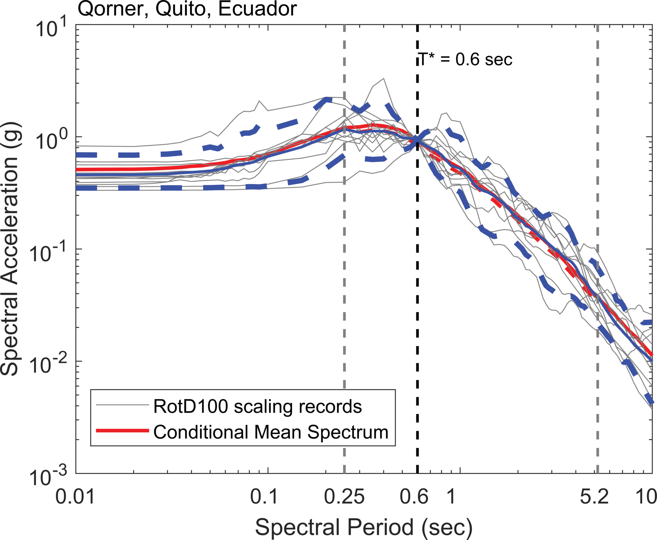
Figure 12. Conditional Mean Spectra (CMS).
To achieve this multistory behavior, temporary steel columns were used during construction, which needed to be left in place until all the floors of a specific cantilever group were cast and reached a specified strength. Complete installation and uninstallation of the temporary steel columns were specified as part of the engineering design, including the required axial strength of up to 559 tf.
The other challenge was that inelastic action of the multistory cantilevers was to be avoided, so that their resistance was not compromised and gravitational load redistribution was avoided.
To achieve that goal, the objective was that most of these beams remain elastic, and if some of them that go into the inelastic range, they achieve a plastic rotation less than the immediate occupancy limit declared by the ASCE41 standard.
Achieving this is not only a matter of over-reinforcing the beams, since brittle shear failure needs to be avoided. The structural strategy was to limit the lateral deformation, and therefore the internal stresses caused by the earthquakes, to a level where the transfer elements remain elastic for the MCE. To achieve this, a first approach using both stiffness and supplemental damping (provided by friction dampers on the coupling beams) was evaluated, but f inally the supplemental damping was discarded, because the stiffness by itself and the energy dissipation of the diagonally reinforced beams were able to reduce the lateral displacements to the desired levels.
“The maximum interstory drifts are on average near one percent for the MCE, well below the maximum of three percent allowed by the LATBSDC code."
Nonlinear Dynamic Analysis Results
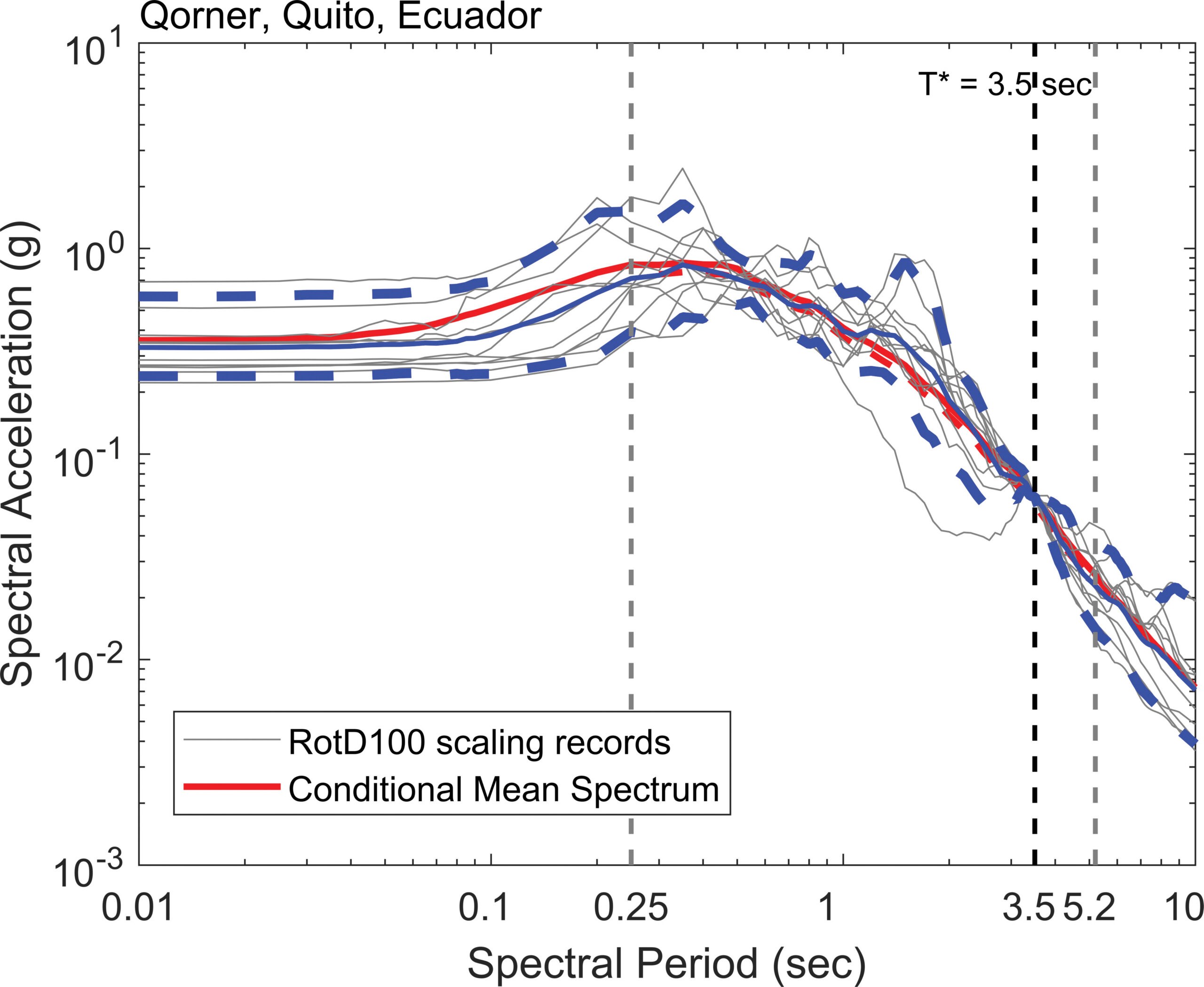
For the nonlinear dynamic analysis of the MCE condition, records scaled to two conditional means spectra were used. The Uniform Hazard Spectrum and its two Conditional Mean Spectra were obtained specifically for the site by Gensis, a seismology company. The two CMS can be seen in Figure 12.
The maximum interstory drifts are on average near one percent for the MCE, well below the maximum of three percent allowed by the LATBSDC code, which is an expected behavior, since the selected strategy is to provide large stiffness and maximize the energy dissipation on the coupling beams (see Figure 13).
Shear and moment envelope for the whole structure, and for each record can be seen in Figure 14. As can be seen, there is a strong influence of higher modes, which increase the shear force demand in the whole structure, with an envelope shape similar to that required by local code, but with a limited base amplification of app 2.5, instead of the value of 5.0 required by the prescriptive code.
Shear failure was avoided for all element parts of the lateral load-resisting system, which was expected, since capacity design principles were used. As an example, normalized axial stress on a specific wall leg and the actual normalized capacity is shown in Figure 15.
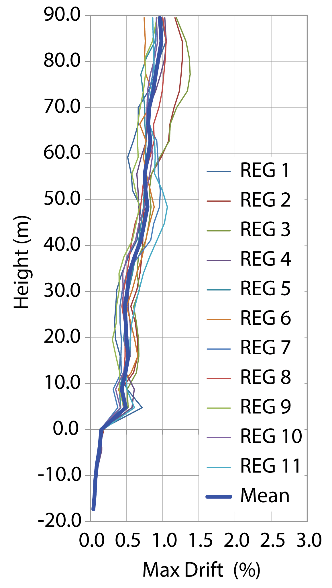
Figure 13. Stiffness of coupling beams.
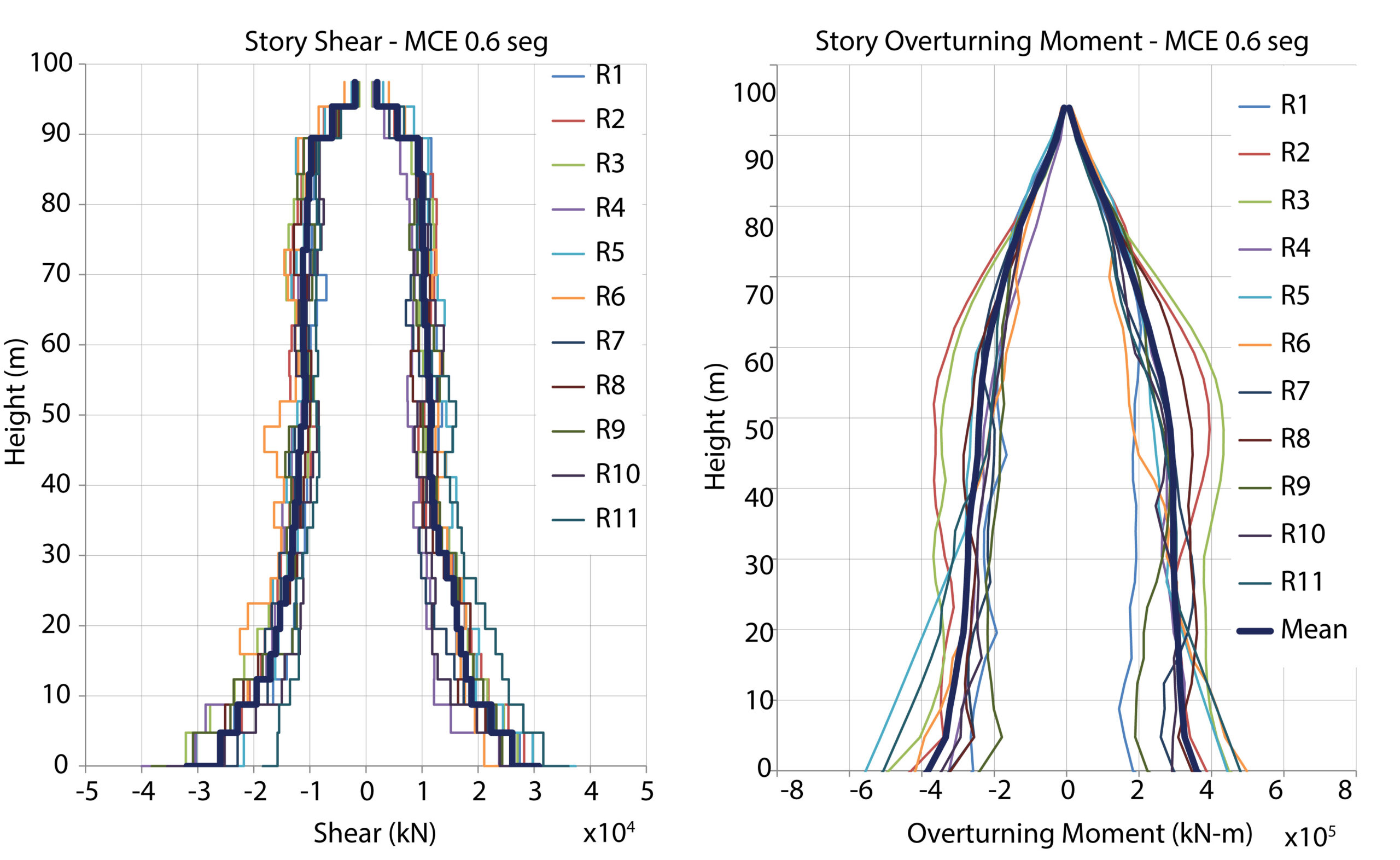
Figure 14. Shear and moment of the structure.
Tensile and compressive strains on core wall boundaries were low, with maximum values of 0.003 and 0.001 respectively, which shows the effectiveness of providing lateral stiffness in order to lower the inelastic demand on the structural elements of the walls (see Figure 16).
Maximum and average demand/capacity (D/C) ratios (associated to a Life Safety Limit according to ASCE41-13) of the coupling beams are shown in Figure 17. As can be seen, the average D/C ratio is below 1.0, and more importantly, the D/C ratios for the two deep coupling beams in the northern façade transfer are 0, which means that they remain elastic, as intended.
On the other hand, the maximum D/C ratios for the sloped column (which are treated as critical force-controlled elements), are 0.62 and 0.67 respectively, which show that they have a strength reserve in case the demand is larger than expected.
Finally, it is shown that, under a condition of immediate occupancy for all the beams of the multistory cantilevers, 76 percent of them have a D/C of zero; that is, they remain elastic for the MCE (see Figure 18). All the remaining beams, with the exception of two, have a D/C ratio well below the immediate occupancy limit. The two sections that have plastic hinge rotation greater than the immediate occupancy have D/C ratios of 0.22 when measured against the limit of life safety, which is the rotation where the strength degradation begins (see Figure 19).
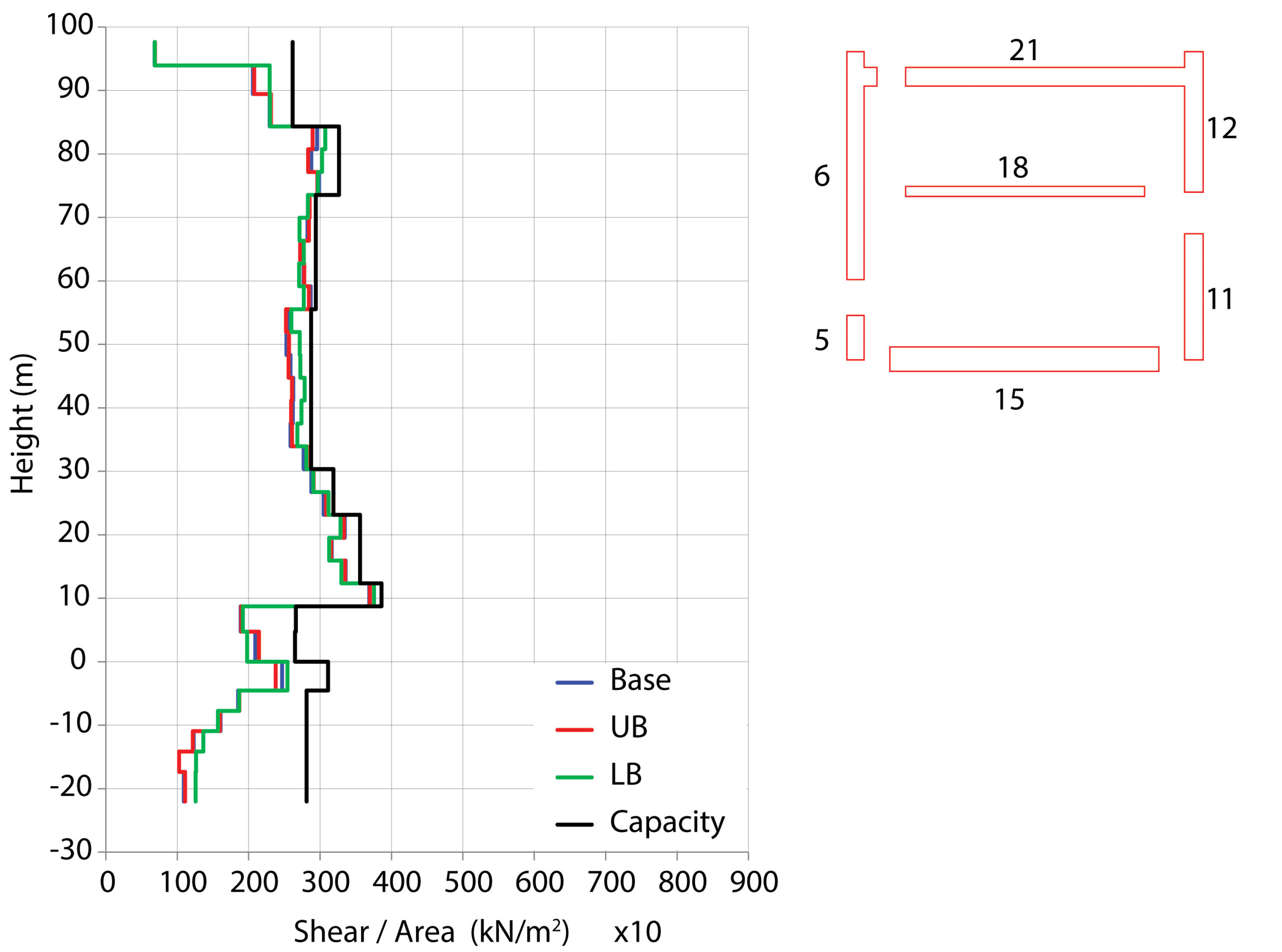
Figure 15. Stress and normalized capacity on wall leg.
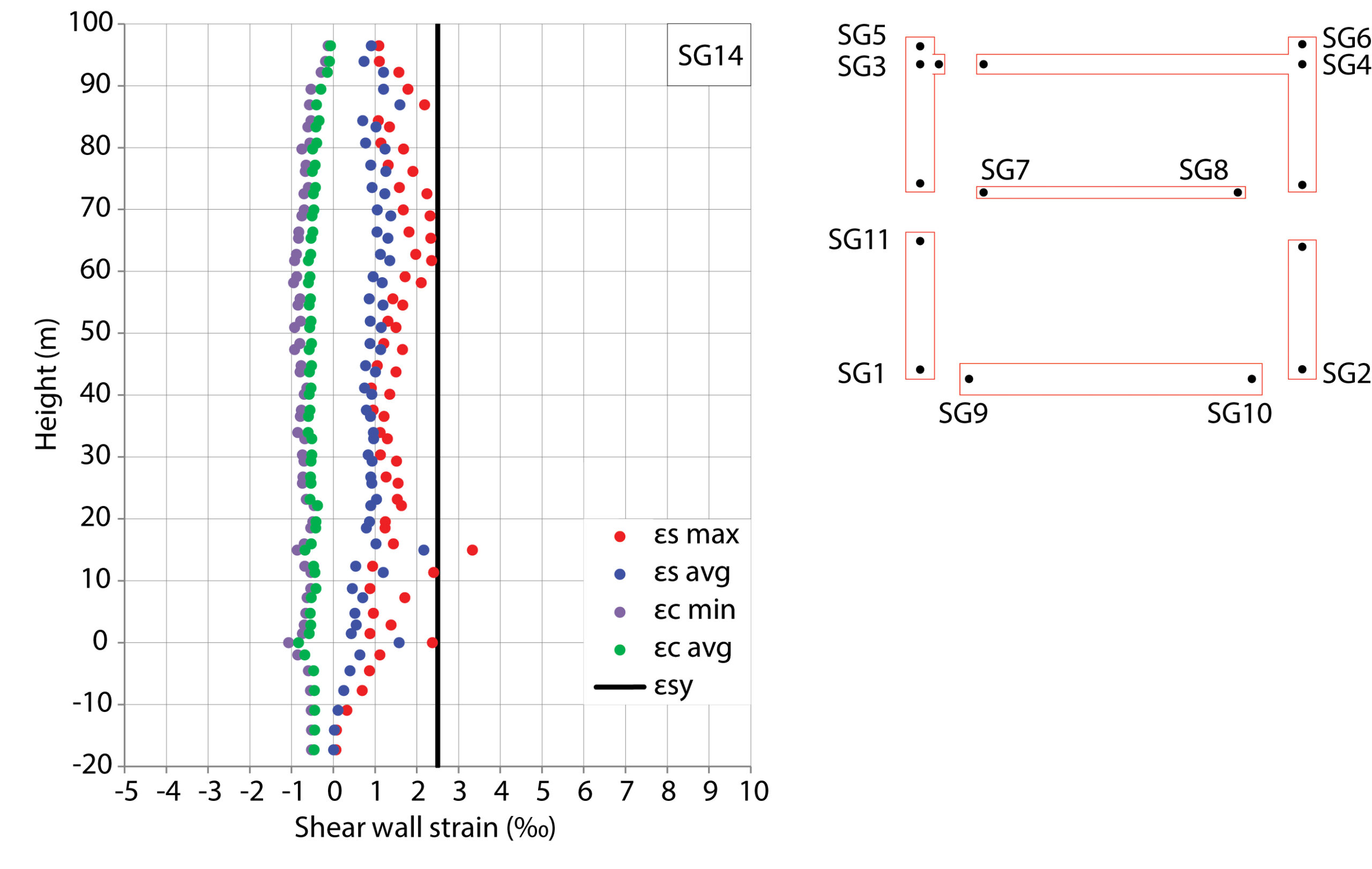
Figure 16. Strain on core wall boundaries.
Conclusions
After analyzing the results, the following conclusions can be made:
- Vertical load transfers generate zones on the vertical load path that will increase their internal stresses during an earthquake.
- These transfer elements need to remain elastic for the maximum considered earthquake (MCE).
- Prescriptive procedures based on linear analysis provide indirect and unreliable methods to achieve this.
- Explicit behavior checks by using performance-based seismic design (PBSD) procedures, which are based on nonlinear dynamic analysis, provide a more reliable and rational method to verify these transfers.
- Increasing lateral stiffness of the building is a good strategy to lower the displacements and therefore the seismic demand on these transfers.
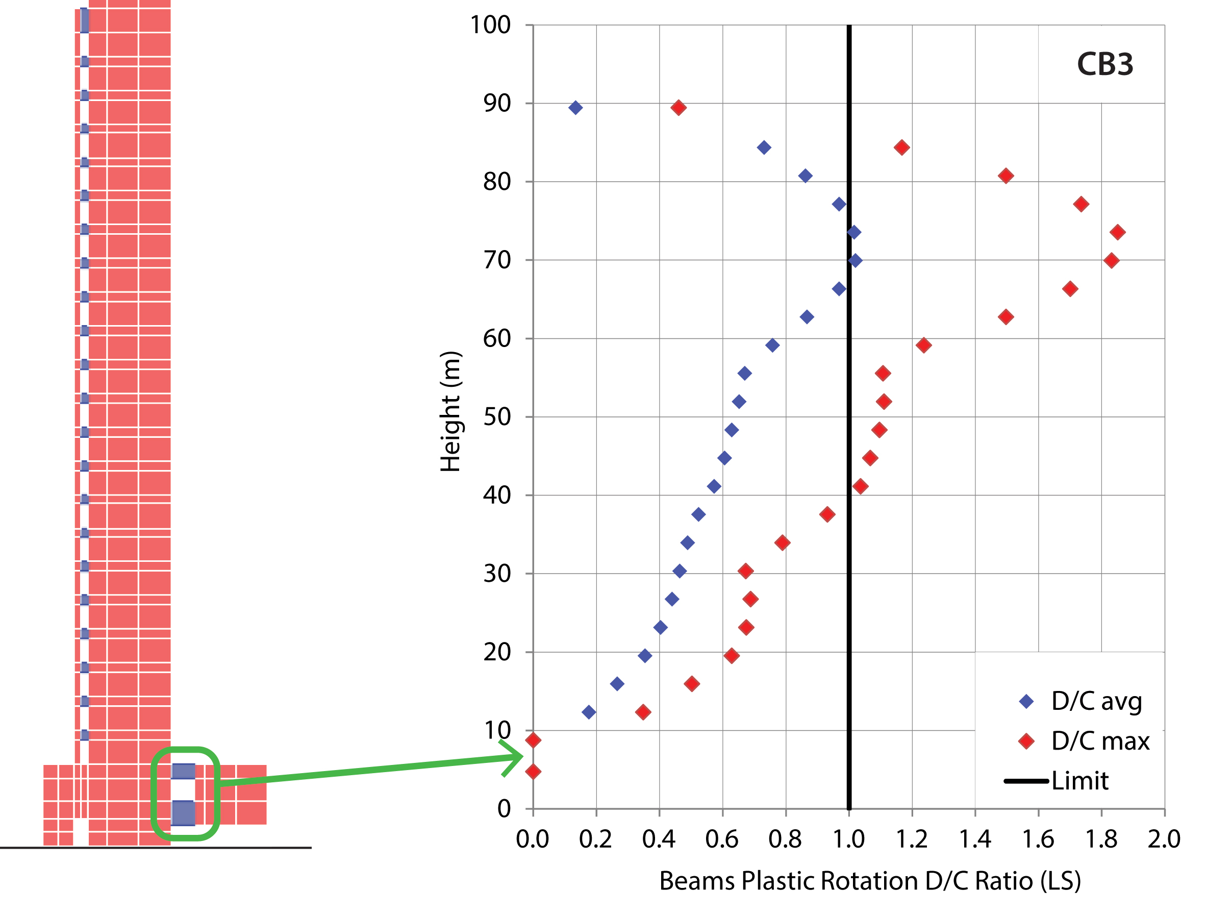
Figure 17. Maximum and average demand/capacity ratios of the coupling beams.
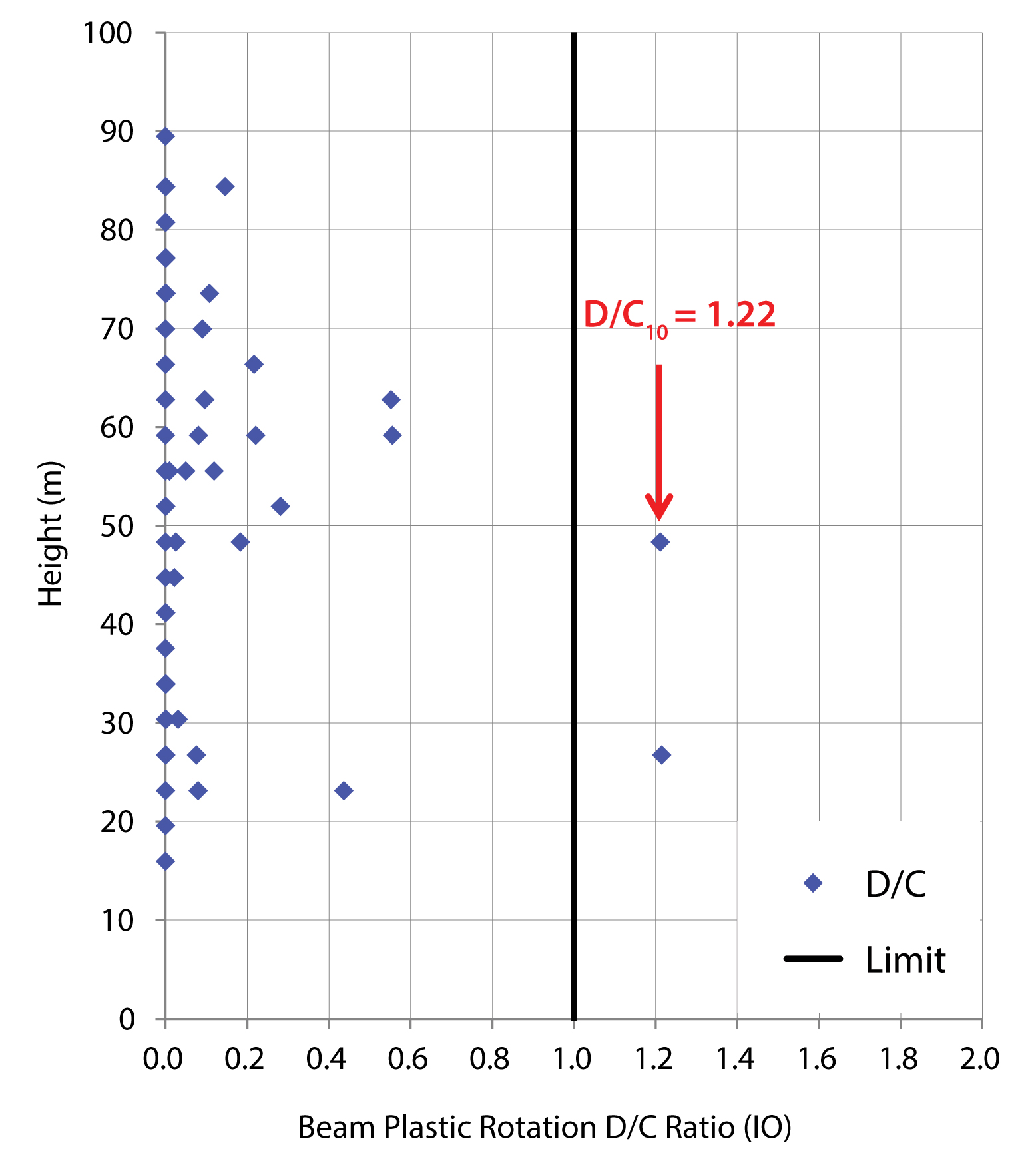
Figure 18. Demand/capacity for beams.
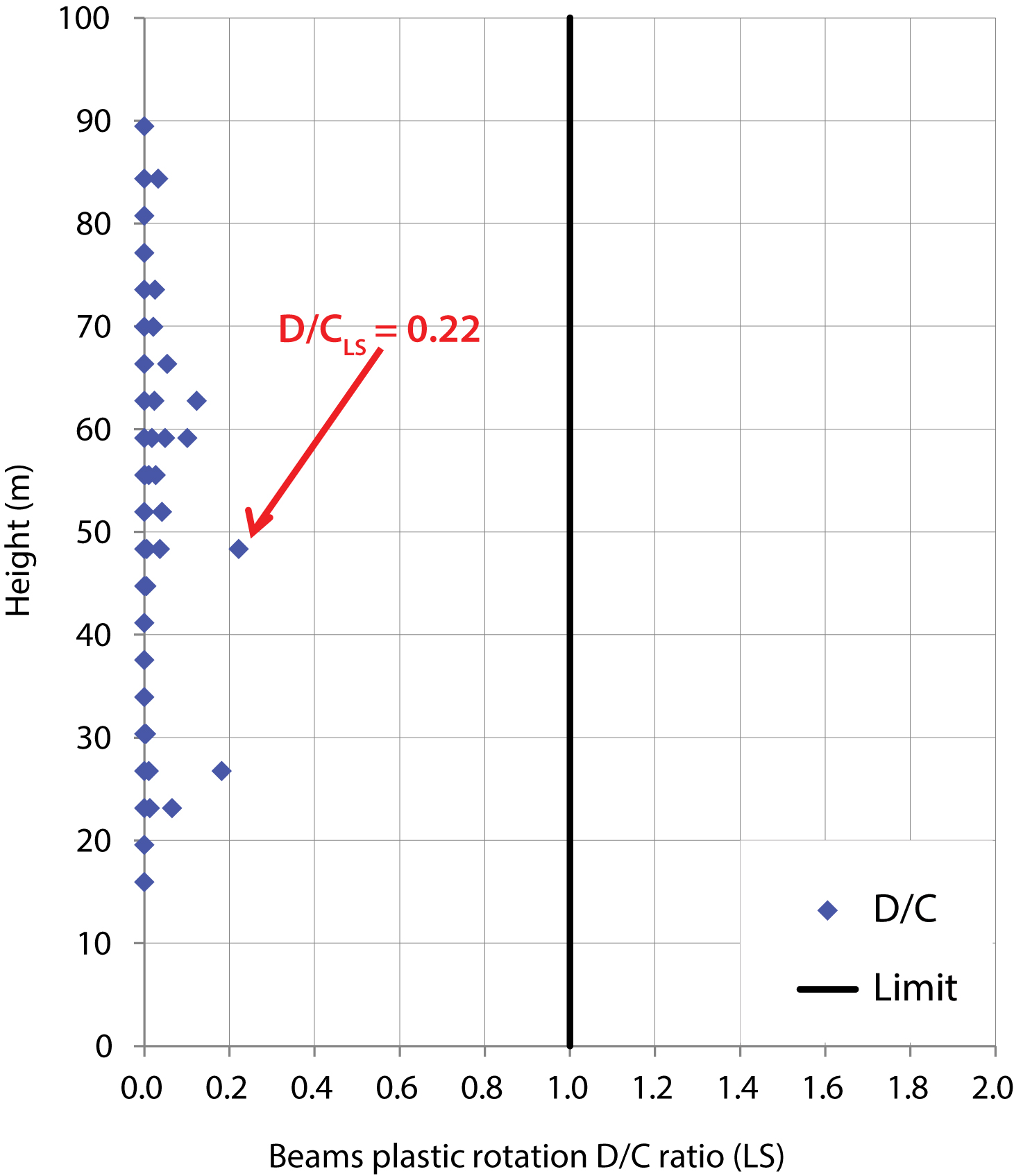
Figure 19. Strength degradation for demand/capacity rotation.
About the Authors
Mario Lafontaine is a partner and seismic technologies director of Rene Lagos Engineers and director of the Chilean Association on Seismology and Earthquake Engineering, ACHISINA. He has participated in the design and peer review of numerous tall buildings located in high-seismicity areas such as Chile, Peru, Ecuador, Mexico, and Bulgaria and is part of several Chilean design codes committees such as Seismic Analysis and Design of Buildings (NCH433), Reinforced Concrete Design (NCH430), Seismic Analysis and Design of Buildings with seismic isolation (NCH2745) and the future code of Performance-Based Seismic Design of Buildings.
Nicolas Maldonado is a structural engineer, graduate from the University of Chile, and project manager of Rene Lagos Engineers, with more than 15 years of experience, being part of several project from the concept design stage to the construction phase, in areas such as Chile, Peru, Ecuador, Bolivia, and Trinidad & Tobago.
Milton Vicentelo is international operations director and partner of Rene Lagos Engineers, currently member of the board of directors and vice president of the Chilean Council for Industrialized Construction (CCI). At CTBUH he is a member of the Americas Steering Committee Group. With more than 20 years as project manager at Rene Lagos Engineers, he has been leading structural engineering teams and managing complex projects in several countries such as Peru, Ecuador, Bolivia, United States, Trinidad & Tobago, México, United Arab Emirates, Bulgaria, and China.
References
American Concrete Institute (ACI). (2014). ACI 318: Building Code Requirements for Reinforced Concrete. Farmington Hills: ACI.
American Society of Civil Engineers (ASCE). (2013). Seismic Rehabilitation of Existing Buildings, ASCE/SEI 41-06. Reston: ASCE.
American Society of Civil Engineers (ASCE). (2016) Minimum Design Loads for Buildings and Other Structures, ASCE/SEI 7-05. Reston: ASCE.
Lagos et al. (1990). The Quest for Resilience: the Chilean Practice of Seismic Design for Reinforced Concrete Buildings. Earthquake Spectra 37 (1): 26–45. https://doi. org/10.1177/875529302097097.
Los Angeles Tall Buildings Structural Design Council (LATBSDC). (2017). An Alternative Procedure for Seismic Analysis and Design of Tall Buildings Located in the Los Angeles Region. Los Angeles: LATBSDC.
Norma Ecuatoriana de la Construcción (NEC). (2014a) Estructuras de Hormigón Armado. Quito: Ministerio de Desarrollo Urbano y Vivienda.
Norma Ecuatoriana de la Construcción (NEC). (2014b) Peligro Sísmico – Diseño Sismo Resistente. Quito: Ministerio de Desarrollo Urbano y Vivienda.